By analysing the shading of continuous surfaces with smooth contours, information on three-dimensional object shapes can be extracted. Using advanced algorithms and special illumination geometries, braille dots and similar types of embossed structures may be checked in an easy and inexpensive way.
Medicament boxes often show information in braille for blind people. Even one missing braille dot may change the information in a potentially dangerous way, and a three- dimensional quality check of braille dots is essential. Additionally, the tests need to be performed in the same way as medicament boxes are normally read by the blind: from the top, regardless of colour labels. Only non-invasive measuring techniques can be applied, as contact methods are too slow and in addition may damage the braille dots. Various 3D measuring techniques [1] were examined, among them laser stripe triangulation, phase shifting and Shape-from-Shading. The latter does not need scanning sensors or special line projectors and is thus the most appropriate for industrial applications.
Shape-from-Shading
Artists like Leonardo da Vinci and Rembrandt created the illusion of depth by virtuous interplay of light and shade (figure 1) with great perfection. The optical measuring principle “Shape-from-Shading” (SfS) reverse engineers this interplay to infer depth. [2]. As a simple example, imagine a dull white object which is illuminated from one side. The illumination causes shading, i.e. shape-dependent intensity distributions resulting in a three-dimensional appearance of the object. If this intensity distribution is recorded by a camera, information on the object shape can be extracted. Figure 2 illustrates variations in the shad- ing of a white cube illuminated from two different angles with fixed positions of cube and camera. Apparently, the two intensity profiles along a horizontal line through the image (marked red in the figure) are remarkably different for the two cases and suggest that such characteristic distributions should be useful for shape analysis.
Principle of the SfS algorithm
The procedure of reconstructing the object shape or “height map” Z(x,y) by SfS works in two steps. In the first step the gradients p and q in x- and y-directions have to be calculated from captured greyscale images. In the second step, a height map is derived by integration of the gradients.
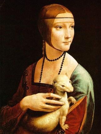
Figure 1: „Woman with Ermine“ by Leonardo da Vinci (Czartoryski Museum, Krakau). The skilfully implemented shading effects of the painting convey an impression of depth
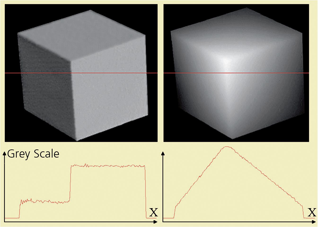
Figure 2: Intensity profiles of a cube illuminated from two different directions
Originally published in German in Photonik 4/2006
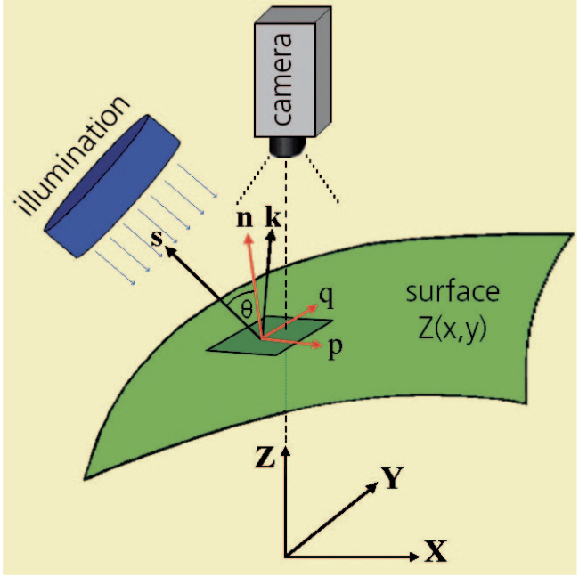
Figure 3: Principle of Shape-from-Shading: The intensity recorded by a camera depends mainly on the angle between the direction vector s of the incident light and the normal vector n of the observed surface element
Without loss of generality the z-axis of the world coordinate system can be chosen to coincide with the optical axis of the camera. The image plane (i.e. the sensor- chip of the camera) is therefore parallel to the xy-plane of the coordinate system. The intensity I(x,y) registered by the camera depends only on the following parameters: the sensitivity c of the sensor, the direction vector s and the intensity Q of the incoming, telecentric (i.e. parallel) light, and the fraction R(n,s) of the light reflected towards the camera (figure 3):
I(x,y) = c·Q(x,y,z)·R(n,s)
The reflectance map R(n,s) describes all details concerning the reflection of light. R depends on the material-dependent and position-dependent reflection coefficients r for diffuse and specular reflection, and on the angle between the direction-vector s of the incoming light and the unknown normal n of the considered surface element. Considering only diffuse reflections (Lambert’s law) thus yields:
R(n,s) = r·cosθ with cosθ = n·s
Note that this result does not depend on the viewing direction of the camera. For suppression of specular reflection, camera and lamps should be positioned in such a way that according to the rule „incident angle = reflection angle“ the specular reflected light is deflected away from the camera lens as much as possible. In addition, the use of blue light is helpful, since specular reflection decreases for shorter wavelengths, depending on the surface roughness.
The intensity recorded in each pixel of the camera corresponding to a volume element of the surface is therefore described by: I(x,y) = c·Q·r·n·s = ρ·n·s
with albedo ρ = c·Q·r
Under these premises, the influences of c, Q and r cannot be separated. They are therefore combined in a single variable known as albedo.
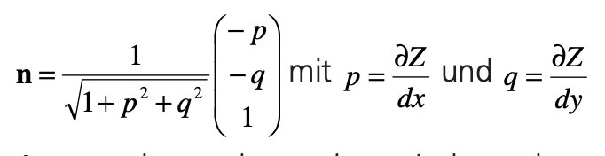
The normal vectors n of the surface elements are defined by the gradients of the surface Z(x,y) in x- and y-direction, i.e. by the partial derivatives of Z(x,y) with respect to x and y:
Apparently, at least three independent equations and therefore at least three pictures for different light directions are required to eliminate ρ and to calculate the gradients p and q. Improved results and an estimation of measuring errors can be achieved if more than three pictures are captured and hence leading to an over- determined systems of linear equations. After solving the equation system using standard methods, a topographical map is calculated by integration over p and q as described in the literature [e.g. 2,3].
Application to braille Inspection
For the development of the braille inspection system DotScan, the SfS method was optimised for this particular application in co-operation with 3D-Shape GmbH, a spin- off of Erlangen University. Due to the fairly large field of view and some geometrical constraints, a few critical measures had to be taken: correction for spherical lens aber- rations, compensation of small deviations from telecentricity and homogeneity of the light sources, low-pass filtering to suppress effects of deformed or bulging packaging and optimisation of the gradient calcula- tions to cope with markings, images and logos (i.e. those usually colour-printed onto medicament boxes) (figure 4). From the pre-processed gradient maps, 3D-data are derived using the formalism described above (figure 5). Subsequent analysis of the cloud of points yields the braille positions in x- and y-directions as well as their heights.

With the help of pattern-recognition methods, the dot samples were compared to braille standards such as Marburg-Medium – these define distances between dots, characters and lines. This comparison must work in a very robust way, since deviations from standardised distances, heights and dot shapes are common. Dots may be pyramids, half spheres and flat-topped with variable diameters. After recognition of the dots they have to be matched to a standard raster in order to group dots belonging to lines of text and to characters within the lines. This procedure is non-sensitive to positioning inaccuracies such as small angles or rotations by 90 or 180°.
Restrictions
SfS yields the shape of objects, but not absolute distances like triangulation systems do. The shape information is derived from the shading of continuous smooth surfaces. The gradients must therefore exist for all surface points and all points must be visible from the camera- and light- positions. No sharp edges and structures that throw shadows are allowed. braille dots fulfill these restrictions easily and are very well suited for the SfS method.
In addition, like many other optical measuring systems SfS expects appropriate surfaces. Transparent or semi-transparent materials and specular reflecting surfaces are unfavourable, since only diffuse reflection is taken into account. Due to the fairly large distance between camera and sample
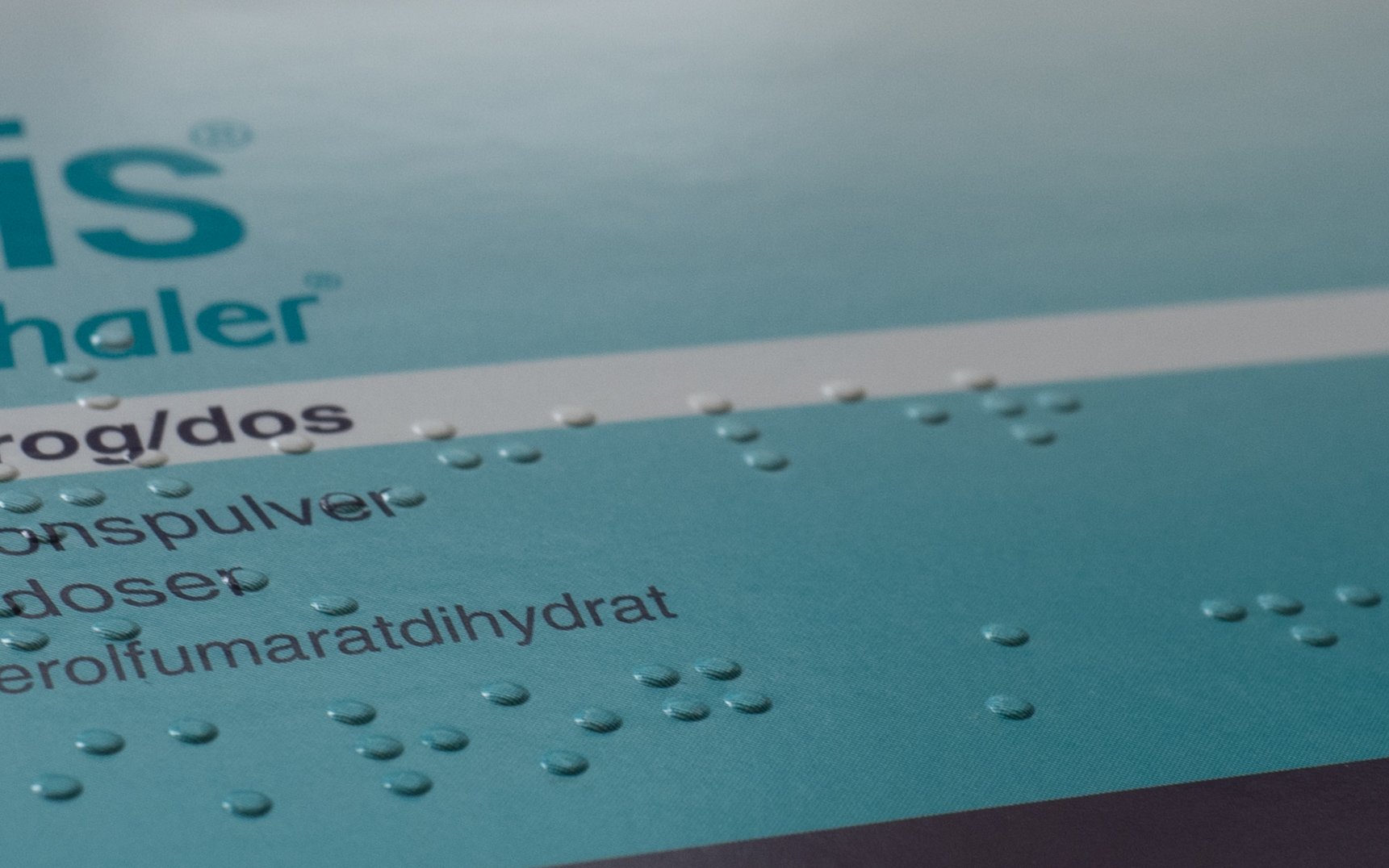
Figure 4: Medicament box with braille dots and colour labelling. Laterally incident light emphasises the raised braille structures
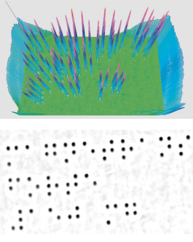
Figure 5: Top: The 3D presentation of the data clearly shows the position, shape and height of the braille dots. Comparison with thresh- olds shows dots which are too high or too low. Bottom: in this picture the height scale is represented by gray values. Interference due to the colour labelling is completely eliminated and due to the short wavelength blue light specular reflections are reduced so far that braille characters could be read safely even on metallic embossing tools.
The inspection system
Based on the SfS algorithm the braille inspection system DotScan was developed. Special emphasis was placed on a user-friendly design, easy handling in an industrial environment and a good cost- performance ratio. This was ensured by close cooperation with partners from the printing and packaging industry. DotScan uses only standard hardware components which are integrated in a 19“-rack (fig- ure 6).
In the upper part of the rack an industrial PC is mounted, the lower part contains a drawer where the samples can be placed. In the measuring volume between drawer and computer four telecentric light sources with blue high-power LEDs are symmetrically positioned and in the centre a high-resolution digital camera is positioned above the samples (figure 7). For each measurement a series of four images is captured, corresponding to each of the four blue LEDs, and stored in the computer. The recording time is 160 ms, notably short in comparison with scanning systems, while analysis depends on the size of the region of interest, a typical value being 300 ms. Resolutions are approximately 100 μm in x- and y-directions and approximately 20 μm in z-direction.
Summary and perspectives
3D inspection systems based on the Shape- from-Shading algorithm are very well suit- ed for analysing continuous, mainly diffusely reflecting surfaces containing braille. Using adaptations of a known algorithm, a robust, quick, user-friendly and affordable inspection system for braille was realised, including fulfilment of the requirements of the packaging industry. Further fields of application include reading and test- ing of embossed printing and engravings, and perhaps less obviously inspection of surface textures, grooves, marks, wrinkle patterns and damage such as scratches, bubbles, blow holes and dents.
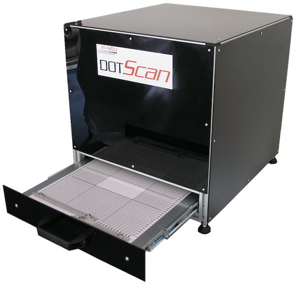
Figure 6: The braille inspection system DotScan
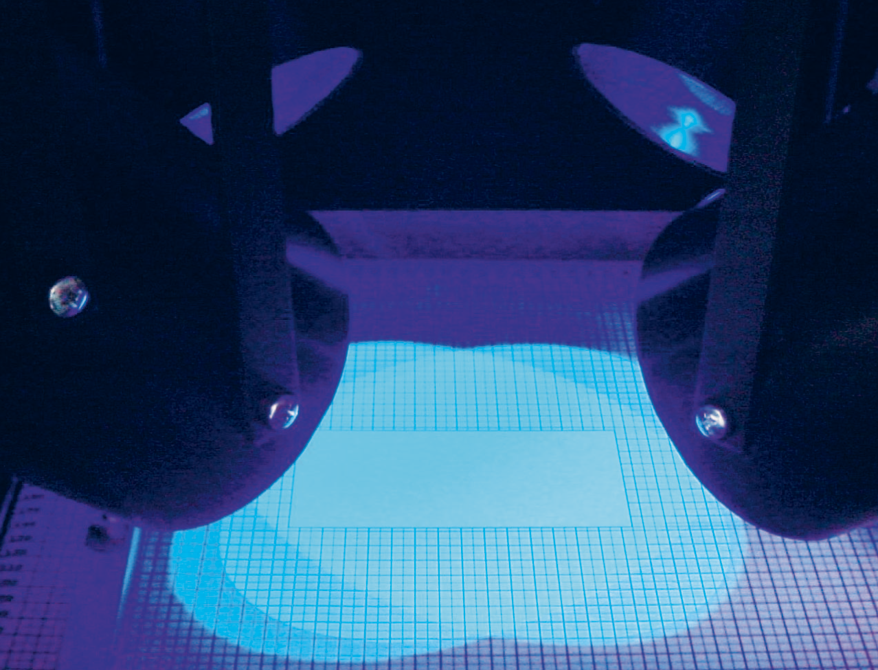
Figure 7: View of the measurement area of DotScan. The four symmetrically positioned telecentric lamps illuminating the measuring field with homogeneous blue light can be easily recognised. Samples can be positioned in a fast and easy way using the magnetic clips attached to the marked measuring field
Future development goals include accounting for specular reflection, enhancement of the z-resolution and optimisation of the speed of operation.
Literature:
-
[1] Y. Shirai, Three-dimensional Computer Vision, Springer, 1987
-
[2] B. Horn, M. Brooks (eds.), Shape from Shading, MIT Press 1989
-
[3] Ch. Wagner, Informationstheoretische Grenzen optischer 3D-Sensoren, PhD thesis at the University Erlangen-Nürnberg, 2003